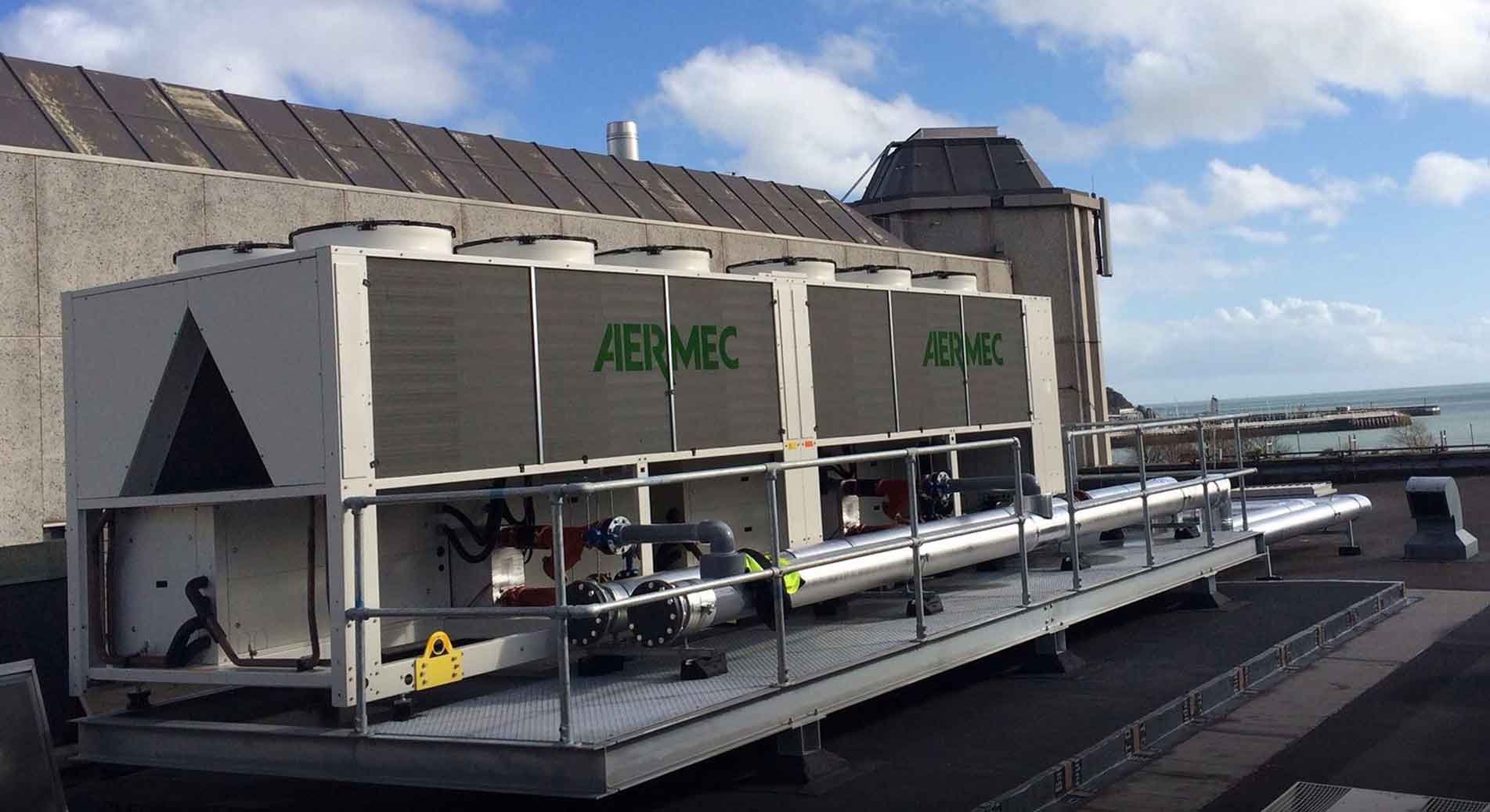
Access the most frequent alarm codes on our air to water ANK heat pumps. Don't see an alarm code listed below? Send our Technical Department an email at aermecservice@mitsair.com for assistance.
101
Compressor thermomagnetic switch. Fan thermomagnetic switch. Pump thermomagnetic switch
This warning appears if the contact of the thermomagnetic switch protecting the MTC compressor is opened.
102
Fan thermomagnetic switch.
This warning appears if the contact of the thermomagnetic switch protecting the MTV fan is opened. This code is displayed only if the card is used as a replacement for cards with SW up to version 3.6.
103
High pressure switch.
This warning does NOT indicate the status of the high pressure switch itself, but of the compressor contactor. The high pressure switch acts directly on the compressor contactor. If the card con-trols the switch-on of the compressor, and the contactor is not activated after 3 seconds, this signal appears. This alarm can also be caused by a defect in the functioning of the transmission system relay from the compressor contactor to the card (indicated as RAP in the wiring diagrams). If the contactor is deactivated while the com-pressor is functioning, this warning reappears. AP.
104
Flow switch. Water differential pressure switch.
This warning appears with the opening of the contact relating to the flow switch or to the differential pressure switch. This alarm is not detected in the first 40 seconds from when the pump is switched on. The machine goes into lockout when the maximum number of flow switch interventions allowed is exceeded. If frost protection mode (and therefore the pump too) is activated in standby, the flow switch status is also controlled. FL/PD.
105
Low pressure switch.
This warning appears with the opening of the contact of the low pressure switch (intake on the compressor) BP.
106
No water inlet probe.
This warning appears when the water inlet probe is disconnected.
107
No water outlet probe.
This warning appears when the water outlet probe is disconnected.
108
Water freeze.
This warning appears when the anti-freeze temperature threshold (installer menu, parameter (6) default: 3°C) of the outlet water is reached. The pre-alarm condition is removed when the outlet water temperature exceeds the setpoint calculated by the card on the basis of an internal algorithm; the anti-freeze alarm is suspended (in heat mode) for 3 seconds from when the compressor is switched on.
109
No force probe.
This warning appears when the force gas probe is not detected.
110
High force gas temperature.
This warning appears when the force gas temperature (SGP probe) exceeds the threshold set in the parameter. The pre-alarm condition is removed with the factory-set temperature (default 125°C).
111
No compressor delivery pressure transducer.
This warning appears when the compressor delivery transducer is not detected and the machine is set in heat pump mode, or the presence of the DCP is set.
112
High pressure.
This warning appears when the transducer detects a delivery pressure greater than the set threshold (default: 40 bar). The pre-alarm condition is removed with the factory-set pressure (default: 38 bar).
113
No defrosting probe.
This warning appears when the defrosting probe is absent and the machine is set in heat pump mode.
114
No compressor suction pressure transducer.
This warning appears when the compressor suction transducer is absent and the machine is set in heat pump mode.
115
Low pressure.
This warning appears when the compressor delivery transducer detects a suction pressure lower than the factory-set threshold in cool mode (default: 4 bar), or in heat mode (default : 2 bar). The prealarm condition is removed when the suction pressure exceeds the envisaged intervention threshold (default equal to 2 bar). The low pressure alarm is suspended in heat mode for 3 seconds from when the compressor is switched on; it is permanently suspended during cycle reverse.
116
Low output.
Whenever the machine is powered, the control checks the behavior of the compressor once only, via the output control procedure. This control can be deactivated by means of the dip-switch.
118
High pressure capacity control.
This warning appears whenever there is a capacity control due to the set threshold being reached. The machine goes into lockout when the maximum number of capacity controls allowed (default 5) is exceeded. With the inverter machine, it also indicates a capacity control due to a high compression ratio.
119
Low pressure capacity control.
This warning appears whenever there is a low pressure capacity control. The machine goes into lockout when the maximum number of capacity controls allowed (default 5) is exceeded.
120
Discharge temperature capacity control.
This warning appears whenever there is a discharge temperature capacity control. The machine goes into lockout when the maximum number of capacity controls allowed (default 5) is exceeded.
121
Bemf error (chiller inverter) – error in the detection of the back emf.
This error is given by the inverter control card and is linked to compressor pickup current problems.
122
Internal communication error.
The inverter control card has internal communication problems.
123
Overcurrent.
Excessive current absorption by the compressor.
124
No charge.
The compressor does not absorb enough current and may operate empty.
125
Incorrect voltage.
The inverter control card indicates an incorrect BUS voltage.
126
Start-up error.
The inverter control card indicates the incorrect start-up of the PMSM motor
127
IPM protection error.
Error on the IGBT.
128
EEPROM error.
Eeprom error on the inverter control card.
129
Compressor stalling.
130
No communication.
The inverter control card does not respond; it may not be powered, or the serial cable may be disconnected, or the A and B signals may be inverted.
131
PFC module.
Error in the PFC inverter module.
132
Excessive temperature of cooling blade.
133
Overcurrent in acceleration. Hardware error.
134
Overcurrent at constant speed.
Hardware error.
135
Over-current in deceleration.
Hardware error.
136
Undervoltage on BUS DC.
137
Overvoltage on BUS DC.
140
PFC Converter Fault Error in the PFC module.
Software error.
141
Overcurrent in acceleration.
Software error.
142
Overload.
143
Over-current at constant speed.
Software error.
144
Over-current in deceleration.
Software error.
145
Compressor not connected correctly.
146
No communication.
147
Error in cooling blade temperature sensor.
151
Irregular condition.
Frequency reduced by over-current or over-temperature protection.
154
Faulty reverse cycle valve.
The reverse cycle valve could be faulty or blocked.
155
Input water high temperature.
The input water temperature has exceeded the value of installer menu parameter (H). There is probably a boiler in the same system. With the third pre-alarm intervention, the machine goes into lockout.
156
Cycle reverse due to high temperature of discharge gas.
This pre-alarm indicates the intervention of a defrosting cycle due to cycle reverse, without respecting the cycle reverse times. The cycle reverse was prompted by the capacity control threshold being exceeded due to the high temperature of the discharge gas (default 130°). This pre-alarm does not cause the compressor to stop, and there is no maximum number of interventions.
157
Read error of the remote probe of the DHW panel.
This pre-alarm indicates a fault in the remote probe, or a problem in communication with the DHW panel. The alarm is only active if parameter (8)=4 in the menu with password = 30.
158
Read error of the outside air temperature probe.
This pre-alarm indicates a fault in the outside air temperature probe when the DCP is present, or when the machine is a heat pump.


