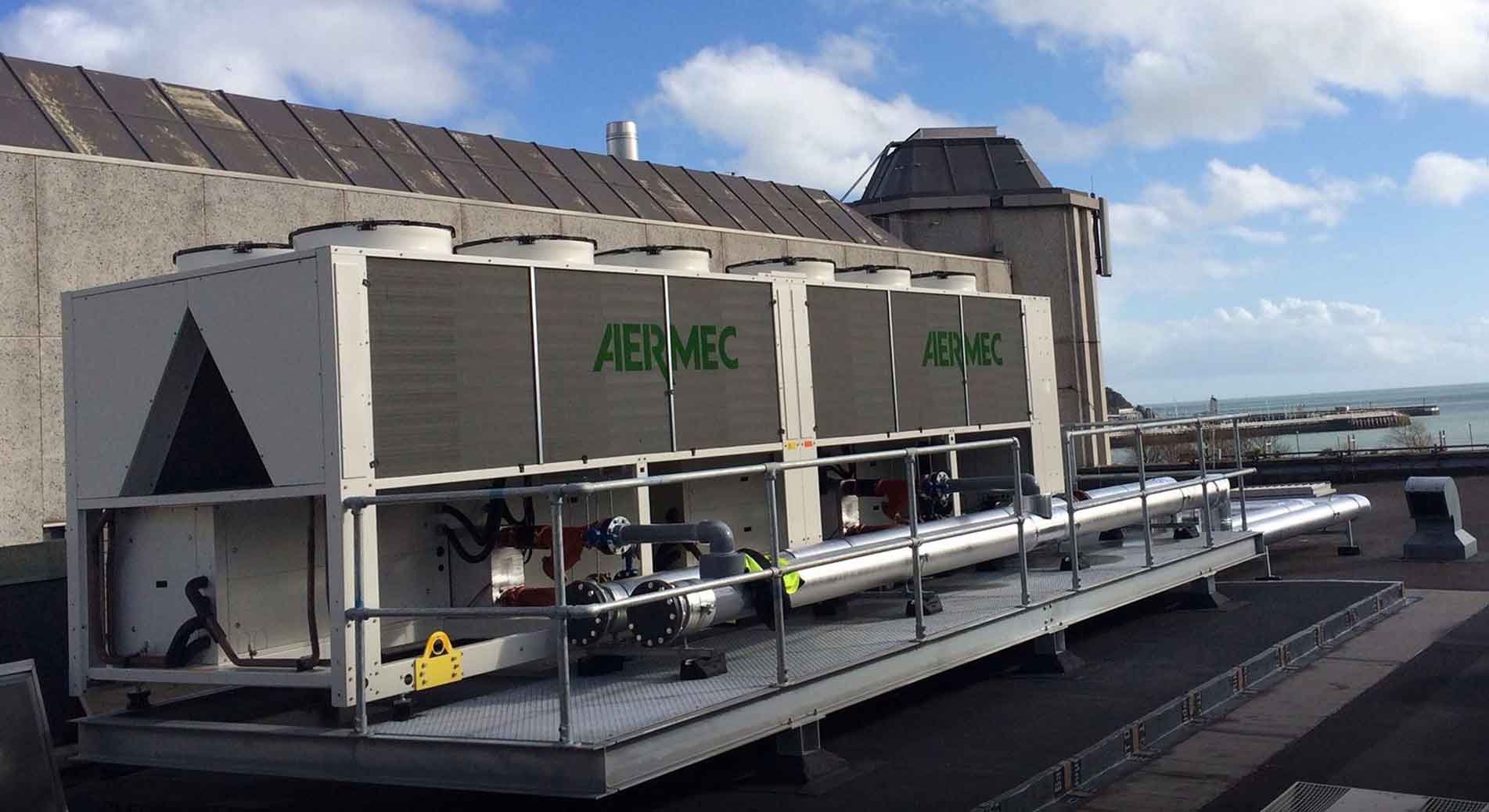
Access the most frequently asked questions (FAQs) on our ANK air to water reversible heat pumps. They can reduce heating costs up to 30% compared with the best conventional systems and condensation boilers. Don't see the answer to one of your questions? Send us an email at aermec@mitsair.com and one of our team members will be happy to assist you.
How many ANK’s can I have working together?
4
What do I need to control multiple ANK’s together?
RS485 Cards for each unit and a Multicontroller (1 for up to 4 ANK’s)
How low can the ANK operate in cooling mode?
68°F ambient with no Low Ambient Kit or 14°F ambient with Low ambient Kit (DCPX)
What is the size of hydronic connections on an ANK?
1 ¼”
Can we get heat tracing and base heater on an ANK?
You can get either but not both.
How do you adjust or test the ANK Moducontrol?
The Moducontrol 4.2 service manual is available from Aermec. The Moducontrol manages the ANK series best when the various parameters remain as factory set points.
What happens if a replacement Moducontrol is a different version number than the original control?
The updated replacement Moducontrol replaces all previous versions of the control. The new module must be addressed via the dipswitches and internal electronic switch according to the new revised manual. New Module Revision Number. Use New Manual. Any new features that are built into the new Moducontrol will automatically be part of the new control features added to that ANK unit. All Moducontrol switches are shipped in the off position. Moducontrol dip switches and control parameters must be set and checked by the mechanic on site for each unit configuration.
How do you reset the Moducontrol back to the factory settings?
Change menu functions by pressing the screwdriver symbol. Enter password 125 by using the arrow keys. Confirm password by pressing the screwdriver symbol again. The Moducontrol display will indicate # 0 or 1. Using the arrow up key scroll to position # 0. Using the screwdriver symbolenter the parameter. Existing parameter should read # 1. Change parameter by using the up arrow and toggle to # 0. Confirm the new setting by pressing the screwdriver symbol. Exit from program menu by pressing the textbook key.
How do you start or stop the unit as a Stand-A-Lone unit?
Change menu functions by pressing the screwdriver symbol. Enter password 30 by using the arrow keys. Confirm password by pressing thescrewdriver symbol again. The Moducontrol display will indicate # 0. Using the arrow up key scroll to position # 0. Using the screwdriver symbol enter the parameter. Existing parameter should read # 0. If not; change parameter by using the up arrow and toggle to # 0. Confirm the new setting by pressing the screwdriver symbol. Exit from program menu by pressing the textbook key.
How do you change the unit from heating to cooling as a Stand- A-Lone unit?
Change menu functions by pressing the screwdriver symbol. Enter password 30 by using the arrow keys. Confirm password by pressing the screwdriver symbol again. The Moducontrol display will indicate # 0. Using the arrow up key scroll to position # 0. Using the screwdriver key enter the parameter. Existing parameter should read # 0. If not; change parameter by using the up arrow and toggle to # 0. Confirm the new setting by pressing screwdriver key. Exit from program menu by pressing the textbook key.
How do you start or stop the unit as a remotely controlled wired unit?
Press the on (1/2 green vertical line on full circle) for 3 seconds. The unit will begin to start if off. The On LED will be displayed.
If not check the following:
Change menu functions by pressing the screwdriver symbol. Enter password 30 by using the arrow keys. Confirm password by pressing the screwdriver symbol again. The Moducontrol display will indicate # 1. Using the arrow up key scroll to position # 9 PAN. Using the screwdriver key enter the parameter. Existing parameter should read # 3. if not; change parameter by using the up arrow and toggle to # 3. Confirm the new setting by pressing screwdriver key. Exit from program menu by pressing the textbook key. Switch on unit to start. Test by stopping and starting system by adjusting remote controls up or down.
How do you change the unit from heating to cooling as a remotely controlled wired unit?
Programming unit for remote control operation above configures this function. Using the remote controls switch from heating season to cooling season. Contact is in heating when open. The reversing valve is energized when closed. Contact is in cooling when closed.
How do you adjust cooling temperature?
Change menu functions by pressing the screwdriver symbol. Enter password 000 by using the arrow keys. Confirm password by pressing the screwdriver symbol again. The Moducontrol display will indicate # 1 Stf. Using the screwdriver key enter the parameter. Existing parameter should read # set temperature. Change parameter by using the up or down arrow and toggle to # new temperature. Confirm the new setting by pressing screwdriver key. Exit from program menu by pressing the textbook key.
How do you adjust the cooling differential?
Change menu functions by pressing the screwdriver symbol. Enter password 000 by using the arrow keys. Confirm password by pressing the screwdriver symbol again. The Moducontrol display will indicate # 2 bnf. Using the screwdriver key enter the parameter. Existing parameter should read # set differential. Change parameter by using the up or down arrow and toggle to # new differential. Confirm the new setting by pressing screwdriver key. Exit from program menu by pressing the textbook key.
What if the unit is to be used as a chiller only?
Change menu functions by pressing the screwdriver symbol. Enter password 000 by using the arrow keys. Confirm password by pressing the screwdriver symbol again. The Moducontrol display will indicate # 0 Sta. Using the screwdriver key enter the parameter. Existing parameter should read # 0. Change parameter by using the up arrow and toggle to # 0. Confirm the new setting by pressing screwdriver key. Exit from program menu by pressing the textbook key.
What if unit is to be as a heat pump?
Change menu functions by pressing the screwdriver symbol. Enter password 000 by using the arrow keys. Confirm password by pressing the screwdriver key again. The Moducontrol display will indicate # 0 Sta. Using the screwdriver key enter the parameter. Existing parameter should read# 1. Change parameter by using the up arrow and toggle to # 1. Confirm the new setting by pressing screwdriver key. Exit from program menu by pressing the textbook key.
How do you adjust heating temperature?
Change menu functions by pressing the screwdriver symbol. Enter password 000 by using the arrow keys. Confirm password by pressing the screwdriver symbol again. The Moducontrol display will indicate # 3 StC. Using the screwdriver key enter the parameter. Existing parameter should read # set temperature. Change parameter by using the up or down arrow and toggle to # new temperature. Confirm the new setting by pressing screwdriver key. Exit from program menu by pressing the textbook key.
Factory Setting 45 deg.C. Radiant Heat 35 deg. C., Fan Coils, Radiators 45 deg. C. Others 55 deg. C.
How do you adjust the heating differential?
Change menu functions by pressing the screwdriver symbol. Enter password 000 by using the arrow keys. Confirm password by pressing the screwdriver symbol again. The Moducontrol display will indicate # 4 bnc. Using the screwdriver key enter the parameter. Existing parameter should read # set differential. Change parameter by using the up or down arrow and toggle to # new differential. Confirm the new setting by pressing screwdriver key. Exit from program menu by pressing the textbook key.
How do I turn the compensation temperature (outdoor / indoor reset) On or Off?
The ANK Moducontrol has the ability to adjust the outlet water temperature being supplied to the building according to the changing outdoor temperature in both cooling and heating modes. The changes in water temperature are the inverse of the falling or rising outdoor temperature. Cooling and heating temperature compensation is available if the function is turned on. Change menu functions by pressing the screwdriver symbol. Enter password 000 by using the arrow keys. Confirm password by pressing the screwdriver key again. The Moducontrol display will indicate # 5 CSt. Using the screwdriver key enter the parameter. Existing parameter should read # 0. Change parameter by using the up arrow and toggle to # 1. Confirm the new setting by pressing screwdriver key Exit from program menu by pressing the textbook key. The 0 value turns the parameter Off. The1 value turns the parameter On.
How do you enable domestic hot water usage?
Change menu functions by pressing the screwdriver symbol. Enter password 030 by using the arrow keys. Confirm password by pressing the screwdriver symbol again. The Moducontrol display will indicate # 1. Using the arrow up key scroll to position # A ASA. Using the screwdriver key enter the parameter. Existing parameter should read # 1. Change parameter by using the up arrow and toggle to # 1. Confirm the new setting by pressing screwdriver key. Exit from program menu by pressing the textbook key.
How do you set up domestic hot water temperature (maximum to 130 deg. F. or 50 deg. C.)?
Change menu functions by pressing the screwdriver symbol. Enter password 000 by using the arrow keys. Confirm password by pressing the screwdriver key again. The Moducontrol display will indicate # 1. Using the arrow up key scroll to position # E SAS. Using the screwdriver key the parameter. Existing parameter should read # set DHW temperature. Change parameter by using the up arrow and toggle to the new DHW temperature. Confirm the new setting by pressing screwdriver key. Exit from program menu by pressing the textbook key.
Unit is running in heating. Moducontrol display indicates a cooling (snowflake) caller. Outdoor Coil is cooling. Indoor Coil is heating.
Change menu functions by pressing the screwdriver symbol. Enter password 333 by using the arrow keys. Confirm password by pressing the screwdriver key again. The Moducontrol display will indicate # 1. Using the arrow up key scroll to position # 3. Using the screwdriver key enter the parameter. Existing parameter should read # 0. Change parameter by using the up arrow and toggle to # 1. Confirm the new setting by pressing screwdriver key. Exit from program menu by pressing the textbook key.
Unit is running in cooling. Moducontrol display indicates a heating (sun) caller. Outdoor Coil is heating. Indoor Coil is cooling.
Change menu functions by pressing the screwdriver symbol. Enter password 333 by using the arrow keys. Confirm password by pressing the screwdriver symbol again. The Moducontrol display will indicate # 1. Using the arrow up key scroll to position # 3. Using the screwdriver key enter the parameter. Existing parameter should read # 1. Change parameter by using the up arrow and toggle to # 0. Confirm the new setting by pressing screwdriver key. Exit from program menu by pressing the textbook key.
How do you set up domestic hot water differential (20 deg. F. or 10 deg. C.)?
Change menu functions by pressing the screwdriver symbol. Enter password 000 by using the arrow keys. Confirm password by pressing the screwdriver key again. The Moducontrol display will indicate # 1. Using the arrow up key scroll to position # F bAS. Using the screwdriver key enter the parameter. Existing parameter should read # set differential. Change parameter by using the up arrow and toggle to the # new differential. Confirm the new setting by pressing screwdriver key. Exit from program menu by pressing the textbook key.
How do you set up time delay for DHW diverting valve? (Use timing to open from valve mfg. + allowance)
Change menu functions by pressing the screwdriver symbol. Enter password xxx by using the arrow keys. Confirm password by pressing the screwdriver key again The Moducontrol display will indicate # 1. Using the arrow up key scroll to position # 8 r in. Using the screwdriver key enter the parameter. Existing parameter should read # 1. Change parameter by using the up arrow and toggle to the #2. Confirm the new setting by pressing the screwdriver key. Exit from program menu by pressing the textbook key.
How do you enable hot water heater or boiler?
Change menu functions by pressing the screwdriver symbol. Enter password 030 by using the arrow keys. Confirm password by pressing the screwdriver symbol again. The Moducontrol display will indicate # 1. Using the arrow up key scroll to position # 8 r in. Using the screwdriver key enter the parameter. Existing parameter should read # 0. Change parameter by using the up arrow and toggle to the # 2. Confirm the new setting by pressing screwdriver key. Exit from program menu by pressing the textbook key.
How do you limit the compressor operation? (During periods of time when boiler integration is taking place)
This error can occur when boiler is following ANK indoor outdoor reset parameters at ODT below 0 deg. C. Change menu functions by pressing the screwdriver symbol. Enter password 030 by using the arrow keys. Confirm password by pressing the screwdriver key again. The Moducontrol display will indicate # 1. Using the arrow up key scroll to position # H Ati. Using the screwdriver key enter the parameter. Existing parameter should read 65 deg. C. Change parameter by using the down arrow and toggle key to 50 deg.C. Confirm the new setting by pressing the screwdriver key. Exit from program menu by pressing the textbook key. Also check the design temperature boiler return (inlet) water setting. Set for 45 to 50 deg. C.
How do you enable flow switch bypass for DHW?
Change menu functions by pressing the screwdriver symbol. Enter password 030 by using the arrow keys. Confirm password by pressing thescrewdriver key again. The Moducontrol display will indicate # 1. Using the arrow up key scroll to position # E bAF. Using the screwdriver key key enter the parameter. Existing parameter should read # 0. Change parameter by using the up arrow and toggle to the # 1. Confirm the new setting by pressing the screwdriver key. Exit from program menu by pressing the textbook key.
How do you set time for Flow Switch Bypass for DHW?
Change menu functions by pressing the screwdriver symbol. Enter password 030 by using the arrow keys. Confirm password by pressing thescrewdriver symbol again. The Moducontrol display will indicate # 1. Using the arrow up key scroll to position # E bAF. Using the screwdriver key enter the parameter. Existing parameter should read # 0 seconds. Change parameter by using the up arrow and toggle to the new # of seconds required . Confirm the new setting by pressing screwdriver key. Exit from program menu by pressing the textbook key.
How to do you set up the ANK to receive BMS commands?
Turn power supply off to unit. Install the Modu485 card into the Moducontrol as described in the provided literature. Connect the shielded three wire 18 to 22 gauge communication cable between the building supplied BMS system and the Moducontrol. Using the installer menu Password 30 make sure parameters J Adi is set to 1, L bdi is set to 1, n Asi is set to 1. Check parameters with technician on site. Your BMS should have access to see and write to the displayed values. Your BMS should have access to up to 142 commands displayed. Some of the commands will not be applicable to your unit as this control is found in ANK’s with optional built in features , ANL’s, ANLi’s, SRP units, etc. The most used commands are on/off (Off = 0, On = 1), heat or cool ( Cool = 0, heat =1) and alarm reset (alarm reset command 1 = reset). Set n Asi back to 0 when completed setup to avoid unintentional rewrites.
No cooling or heating . Error code 101 is displayed on Moducontrol. Compressor, Fan, Pump Thermomagnetic Switch.
If the compressor breaker (MTC) trips the auxiliary switch opens causing the Moducontrol to Alarm. Some units will also alarm if a failure in the pump or fan circuits have a failure depending on the wiring version.
No cooling or heating . Error code 102 is displayed on Moducontrol. Fan Thermomagnetic switch.
If the outdoor fan breaker (MTV) trips the auxiliary switch opens causing the Moducontrol to Alarm. Some units will also alarm if a failure in the pump occurs depending on wiring version. This feature was dropped after Moducontrol 3.6.
No heating or cooling. Error code 103 is displayed on Moducontrol. High Pressure Switch.
This alarm does not indicate the status of the actual high pressure switch but the status of the contactor. If the Moducontol signals the compressor to start the high pressure switch must be closed. If the pressure switch is open the contactor will not pickup; the alarm will trip in three (3) seconds. The HP alarm will also alarm if the compressor is running and the contactor is suddenly deactivated. A broken wire or loose contact in this circuit will also cause an alarm.
No heating or cooling. Error code 104 is displayed on Moducontrol. Flow Switch Error.
If the flow switch or differential switch opens the Moducontrol will alarm and stop the unit. On startup the Moducontrol will allow up to forty (40) seconds for the pump to establish flow before temporarily alarming. The unit will try to start until the number of interventions exceeds the maximum shut downs before going to a permanent alarm.
No heating or cooling. Error code 105 is displayed on Moducontrol. Low Pressure Switch. Chiller option only.
The low pressure alarm appears on the display when the low pressure switch contact opens due to drop in suction pressure at the inlet of the compressor.
No cooling or heating . Error code 106 is displayed on Moducontrol. No Water Inlet Probe.
If the inlet water sensor signal is lost this alarm will be displayed.
No cooling or heating . Error code 107 is displayed on Moducontrol. No Water Outlet Probe.
If the outlet water sensor signal is lost this alarm will be displayed.
No cooling or heating. Error code 108 is displayed on Moducontrol. Water Freeze.
This alarm is displayed when the outlet water temperature reaches three (3) degrees C. The pre-alarm condition is removed when the outlet temperature rises above a calculated setpoint algorithm. A three second startup delay is initiated when the outlet temperature is reached.
No cooling or heating. Error code 109 is displayed on Moducontrol. No Force Probe.
This warning is appears when the force gas probe is not detected due to poor connections or failure of probe.
No cooling or heating. Error code 110 is displayed on Moducontrol. High Force Gas temperature.
SGP probe exceeds threshold set in parameter. Factory set temperature default is 125 deg. C. (257 deg. F.) . The compressor discharge temperature is to high, check refrigerant charge, TXV, superheat and operating limits.
No cooling or heating. Error code 111 is displayed on Moducontrol. No compressor delivery pressure transducer.
Heat pump error when delivery pressure transducer signal is absent. Check wire to transducer and transducer. Also active if DCPx is not set correctly.
No cooling or heating. Error code 112 is displayed on Moducontrol. High Pressure.
High pressure transducer detects high delivery pressure above 40 deg. C. (104 deg. F.).
No cooling or heating. Error code 113 is displayed on Moducontrol. No defrosting probe.
Heat pump error when defrost transducer signal is absent. Check wire to transducer and defrost transducer.
No cooling or heating. Error code 114 is displayed on Moducontrol.
Heat pump error when transducer signal is absent. Check wire to transducer and suction transducer.
No cooling or heating. Error code 115 is displayed on Moducontrol. Low Pressure.
Indicate low pressure below 4 bar ( 58 psig. ) in cooling mode or 2 bar (29 psig. ) in heating mode. Pre-alarm will reset when pressure exceeds set point by 2 bar (29 psig.) The low pressure alarm is bypassed for 3 seconds in heating mode and permanently bypassed from reverse cycle when compressor is switched on.
No cooling or heating. Error code 116 is displayed on Moducontrol. Low output.
The Moducontrol checks the performance of the compressor performance once during the cycle. Performance is measured at 40 seconds from the start of the compressor. Parameter can be turned off by using #4 dipswitch on Moducontrol.
No cooling or heating. Error code 117 is displayed on Moducontrol. Pump breaker Switch.
The Moducontrol indicates a tripped breaker (MTP) in the pump circuit. Check pump. Function deleted after version 3.6.
No cooling or heating. Error code 118 is displayed on Moducontrol.
This error/alarm is not used anymore. The error occurs whenever the high pressure / capacity control transducer indicates a high pressure event. After five (5) prealarms the Moducontrol will lockout the unit.
No cooling or heating. Error code 119 is displayed on Moducontrol.
This error/alarm is not used anymore. The error occurs whenever the low pressure/capacity control transducer indicates a low pressure event. After five (5) prealarms the Moducontrol will lockout the unit.
No cooling or heating. Error code 120 is displayed on Moducontrol.
The error occurs whenever the discharge temperature / capacity control transducer indicates an event. After five (5 ) prealarms the Moducontrol will lockout the unit.
No cooling or heating. Error code 123 is displayed on Moducontrol. Over current.
The compressor is drawing to much current either in starting up or running. Check voltage and current flow. Check capacitors, soft starter, wiring, compressor windings and contactor contacts.
No cooling or heating. Error code 124 is displayed on Moducontrol. No charge.
The compressor is running with extremely low current and may not have enough refrigerant. Check refrigerant charge, superheat, and subcooling.
Check soft starter, capacitors, compressor windings, contactor, and wiring. Check voltage and amperage. Check condition of the condensing coil. Check for items limiting heat rejection.
No cooling or heating. Error code 129 is displayed on Moducontrol. Compressor stalling.
The compressor is running with extremely low current and may not have enough refrigerant. Check refrigerant charge, superheat, and subcooling.
Check soft starter, capacitors, compressor windings, contactor, and wiring. Check voltage and amperage. Check condition of the condensing coil. Check for items limiting heat rejection.
No cooling or heating. Error code 142 is displayed on Moducontrol. Overload.
Check soft starter, capacitors, compressor windings, contactor, and wiring. Check voltage and amperage. Check condition of the condensing coil. Check for items limiting heat rejection. Check refrigerant levels.
No cooling or heating. Error code 145 is displayed on Moducontrol. Compressor not connected properly.
Check all wiring and electrical components to compressor.
No cooling or heating. Error code 154 is displayed on Moducontrol. Faulty reversing valve error.
The reversing valve could be faulty or blocked. Check wiring and coil. Check valve to see if it is bypassing hot gas.
No heating or cooling. Error code 155 is displayed on Moducontrol. High input water temperatures.
High temperature boiler water has entered the loop at a value above the set point entered into the moducontrol. See parameter H. Moducontrol will lock out system on the third occurrence.
No heating or cooling. Error code 156 is displayed on Moducontrol. Cycle reversal due to high pressure.
The unit has gone into defrost without waiting for the correct time between defrosts to be completed. The capacity control threshold was terminated due to high discharge temperatures (130 deg. C.). This pre-alarm does not cause the system to stop and there is no limit to the number of interventions.
No cooling or heating. Error code 157 is displayed on Moducontrol. DHW remote probe error in tank
The DHW temperature probe has a fault. Check sensor and control wiring. This function is only active if parameter 8 = 4. Use password 30.
No cooling or heating. Error code 158 is displayed on Moducontrol. Outdoor temperature probe reading error.
Alarm occurs if DCPX is present or unit is configured for heat pump mode. If an error exists with the outdoor temperature probe reading. Check wiring to sensor and sensor. Alarm occurs when DCPX and heat pump.
How do you reset an ANK alarm?
In order to reset an alarm you must push the red bell reset button until the small red alarm bell indicator disappears. Turning the unit disconnect or on off switch will not clear any alarms. Manual reset controls and breaker switches must be reset manually prior to using the reset button if tripped.
How do you reset an ANK alarm with a BMS system installed?
If the alarm has been caused by a safety switch which will automatically reset the BMS can reset the ANK Moducontrol. The BMS can reset an alarmed Moducontrol if the Serial Communication Protocol digital line 5 parameter 0 can be switched to 1. Manual reset controls and breaker switches must be reset manually prior to using the BMS in order to successfully start the unit.
The outdoor fans do not start or run properly in cooling or heating modes
The Moducontrol starts the outdoor fans a few seconds after the compressor starts and allows the fans to run to the end of the cooling or heating caller. The compressor stops and the fans continue to run for a few seconds afterword. Check the wiring connections at the MTA, Moducontrol ( M1S-1, M1-1), fan run capacitor and motor lead connections. Check fan, run capacitor with capacitor tester All fans are 230 volt single phase. Check the fan windings for short, open, or grounded conditions.
The outdoor fans do not start, stop or operate properly in heating defrost mode.
The Moducontrol shuts off the compressor and condenser fan motors when the defrost mode starts. The Moducontrol then stops the compressor and switches the position of the reversing valve to warm the outdoor coil. The compressor is then turned back on. The ice and frost build up on the outdoor coil melts and drains away. The Moducontrol then stops the compressor and switches the position of the reversing valve to the heating mode. The compressor resumes in the heating mode after the time delay is completed. The system water pump runs all the time through the defrost process.
The outdoor fans do not start or run properly with DCPX / Penn P66AA-1C speed controller.
The Moducontrol supplies 0 to 10 volts dc and 230 volts ac to the Penn P66AA-1C. The Speed Controller ramps up to 90 % of the normal fan speed for 7 seconds and then begins to modulate to the required speed. The Speed Controller provides power to the fan motor for as long as the cooling caller exists. As soon as the cooling caller is complete the Moducontrol stops the 0 to 10 vdc and line voltage shutting off the fan motors several seconds later.
Check the fan components and wiring as above. Check position of dipswitch # 7 on the Moducontrol. Switch # 7 must be On. The Moducontrol sends0 to 10 vdc fro m M6-3 and M6-4 to E3 and E4 of the speed controller. The speed controller must have 24 volts at terminals E1 and E2 from an independent transformer. Speed controller terminal L receives power from the Moducontrol terminal M1S-1. Terminals L and M of the speed controller close to provide power to the fan motors.
What causes the outdoor fan to modulate in the domestic hot water mode?
The Moducontrol switch # 7 identifies the requirement for fan modulation and adjusts the speed accordingly in DHW mode. The Moducontrol also provides fan speed modulation for low temperature cooling and mild temperature heating callers as required.
What causes the outdoor fan to modulate in the domestic hot water mode?
Moducontrol dipswitch # 7 to on. Set parameter A to 1. Set parameter E to 1. Set parameter F is set between 60 and 300 seconds depending on the time required to open the three way valve. The TWS switch automatically overrides the space heating controls to provide hot water. Please Note installer level index 0 parameter iu must be set to 2. Domestic hot water heating is only possible if a remote storage temperature sensor, 3-way valve, domestic hot water storage tank and DCPX-Penn Johnson control have been installed. Please note installer level index 0 parameter iu must be set to 2. The compressor is turned off for 5 minutes when shifting from space conditioning to DHW heating. On completion of the DHW command the compressor will shut off for 5 minutes before returning to addressing the space conditioning requirements.
What controls are recommended for DCPX control of chillers and heat pumps?
The SAGInoMIYA RGE pressure actuated speed controller can be used on ANK series units designated as chillers only. The Johnson Controls P66AA-1C speed controller is approved for chillers and heat pumps. It is necessary for Domestic Hot Water Production (DHW). Required for Cooling Operation below 20 Deg. C. Required for mild weather space heating and DHW production.
How do you set up the ANK series units to produce Domestic Hot Water (DHW)?
The production of hot water can be handled in two different ways. Integrated and free standing. The most common method is to integrate the process completely into the ANK control system.
(1) Integrated Operation
The DHW thermostat sensor is to be installed into the storage tank. The control wires from the DHW thermostat send a signal to a three way diverting valve to switch position and change the flow of the water from the space heating and cooling circuit to the DHW storage tank circuit. When the end switch (dry contacts) on the 3 way diverting valve closes the ANK terminals T-10 and T-11 indicate to the Moducontrol that DHW has priority over all other operations. The ANK will start up and continue to heat DHW until the DHW thermostat sensor is satisfied at which time the diverting valve will return to heating or cooling the space as the end switch opens. As soon as the end switch opens the ANK resumes control of the space conditions.In order to heat domestic hot water the ANK series units must be fitted with an outdoor fan speed controller to eliminate nuisance high pressure cutouts during the summer months.
The set up of an ANK for domestic hot water production requires the following changes to the unit to be made prior to start-up:
1. Install DCPX control as per distributors suggested instructions2. Switch Moducontrol switch position 7 to on3. Change Moducontrol programming for flow switch bypass4. Set password 30 parameter A to 15. Set password 30 parameter E to 1 6. Set password F to 180 seconds. To allow valve to fully open before Domestic hot water production starts7. Set domestic hot water temperature as required. Lowest DHW temperature below 50 deg. C. acceptable by client works best
(2) Stand-a-Lone Operation
In this mode the ANK does not take over the full heating control of the domestic hot water operation. The heating of the storage tank is completed in two stages as the ANK preheats the incoming wiring and a secondary water heater (electric or gas) completes the process. The on board storage tank thermostat is used as a second stage heating control is separate from the ANK system and allows for an independent heating of the DHW in the event stage one heating is not active. Terminals T-12 and T-13 are not connected in this scenario.
Heat pump shuts off occasionally on hot day due to high pressure switch trips while heating hot water.
Install the DCPX control to manage the heat rejection from the ANK to the DHW system as the tank comes up to temperature.
Spring maintenance. Make sure the outdoor condenser coil has been cleaned with a soft water spray.
Heat pump shuts off occasionally on hot day due to high pressure switch trips while heating hot water.
Set the maximum hot water temperature not to exceed 50 Deg. C. or 131 Deg. F. (Factory max. 60 deg. C or 140 Deg. F.).
Heat pump shuts off occasionally due to flow switch error.
Set timing for the heat pump to start heating DHW after the diverting valve has fully opened. (Change password 30 parameter E to 1. Change password 30 parameter F to 180 sec).
Heat pump shuts off occasionally on hot day due to high pressure switch trips while heating hot water.
Make sure circulation pump is free of air and is running.
Heat pump shuts off occasionally on hot day due to high pressure switch trips while heating hot water.
Check piping system for partially closed valves or trapped air. Make sure circulation pump is free of air and is running.
The circulation pump does not work.
On units equipped with a circulation pump the Moducontrol starts the circulation pump a few seconds after the cooling, heating or DHW caller is recognized. The pump continues to run as long as the Moducontrol receives a demand call.
Check the wiring connections at the MTA, Moducontrol (M1S-2, M1-2) and pump motor lead connections (wires 9 and 13). All pumps are 230 volts single phase. Check the pump windings for short, open, or grounded conditions. Remove the center cap on the pump. Using a screwdriver turn the pump shaft to test the tightness of the bearing. Pump should spin freely. Turn pump shaft several turns. Reinstall cap. Bleed air. Start and test. Check for closed valves in return or supply water.
The circulation pump does not work. Motor is hot.
Pump motor has 230 volts. Current is not measurable. Pump motor has impedance shunt to eliminate motor burnout. No rotation. Place compass on motor shaft. Observe rotation. None. Flow switch open. Replace pump assembly.
The circulation pump is noisy. (Groaning sound, swishing sound).
Check the pump for air. Loosen the center cap 1/4 turn to vent any air in the pump. Use the air vent bleed cap on the side unit to vent any air at the top of the evaporator waterside inlet. If the unit is equipped with a storage tank vent the expansion tank at the air vent mounted on the tank. Check the water pressure in the system. Minimum operating pressure is 1.5 bar or 21 psig. Vent the remainder of the high points in the system for air.
The circulation pump is noisy. (Whining sound, rumbling sound).
Isolate outdoor unit. Relieve water pressure to zero. Turn off electricity. Disassemble pump. Look for broken impeller, worn impeller or out of balance impeller. Look for dirt build-up on internal surfaces. Clean or replace components if necessary. Reassemble pump. Start and test.
Pump is running. Low suction pressure in cooling mode.
Check all isolating, modulating, switchover, and branch valves to make sure they are open. Check filter to make sure it is not plugged.
Pump is running. High discharge pressure in heating mode.
Check all isolating, modulating, switchover, and branch valves to make sure they are open. Check filter to make sure it is not plugged.
Pump is running. Flow switch is chattering or open.
Check all isolating, modulating, switchover, and branch valves to make sure they are open. Check filter to make sure it is not plugged.
Pump is running. Low pressure drop.
Check all isolating, modulating, switchover, and branch valves to make sure they are open. Check filter to make sure it is not plugged.
What is the minimum pipe size required to pipe the unit properly?
The minimum pipe size recommended by the manufacturer is 1.25 ” inside free cross sectional area for all ANK units. System that share multiple units on a common supply or return must have an equivalent inside free cross sectional area to maintain the flow of water to all units without an excessive pressure drop.
What is the minimum amount of water (GPM) to be circulated in the loop?
Chillers require slightly less water circulation than heat pumps. The required water flow rate is higher for heat pumps due to the need to complete a successful defrost cycle in the heating mode.
| Model | Cooling GPM | Heating GPM |
| ANK030 |
7 |
8 |
| ANK045 |
9 |
12 |
| ANK050 |
11 |
13 |
What is the minimum volume of stored water content required to operate an ANK series unit?
The recommended volume of stored water is 10 liters per kilowatt ( or 9.3 gal/ton) in order for the ANK series unit to work properly. The minimum value is 4 liters per kilowatt.
| Model |
Normal Capacity |
Factory Tank | Min Clg. Content |
| ANK030 |
2.51 T |
26 Gal |
23 Gal |
| ANK045 |
3.35 T |
36 Gal |
31 Gal |
| ANK050 |
4.02 T |
36 Gal |
37 Gal |
What is the maximum volume of water allowable in the distribution loop?
The maximum stored water content is determine by the size of the expansion tank that has been installed. The system can operate with between 4 and 10 liters per kilowatt. If the stored water content is greater than 10 liters per kilowatt a larger expansion tank will be required. Higher stored water content improves winter defrost operation.
What is the recommended pressure inside the expansion tank prior to charging the system with water?
The expansion tank is factory charged at 1.5 bar when empty. It can be charged with a maximum of up to a 6 bar. The formula is:
bar = 14.5 psig
P (Bar) = H (m) / 10.2 + 0.3 or P (psig) = H (ft) / 0.433
Charge vessel to calculated pressure before installing water/glycol mixture to loop.
What is the advantage and effect of adding glycol to the distribution loop?
Glycol mixtures provide valuable inhibiters to extend the life of the system as well as providing freeze protection. Glycol reduces the heat transfer characteristics of the system. The lowest amount of inhibited glycol that provides freeze protection is the correct % level.
How much glycol is required to be added to the distribution loop?
Glycol / water mixtures are required in all systems where the exposes exterior piping inside and outside the unit experience outdoor design temperatures below the freezing point of water. Glycol must have a minimum percentage of 20% glycol mixture to avoid the possibility of algae formation inside the piping system. the operating mixture percentage of the glycol / water mixture is dependent on the outdoor temperature to be experienced in the area of installation. See the glycol’s manufactures instructions for the correct mixture levels.
Why do I require glycol / water mixture in my system?
Glycol / water fluid mixtures generally contain inhibitors that protect the inside of the piping system from corrosion caused by electrolysis. As well small dirt or rust particles may be kept in suspension longer until captured by the in-line filter which will reduce maintenance issues. The effective cooling range may be adjusted slightly lower by reducing the loop temperature if required in some systems. All chillers and heat pumps that are exposed to outdoor temperature below the freezing point (32 Deg. F. or 0 Deg. C.) all require treatment with glycol additives.
How much glycol do I need in my system?
Each system will require a different amount of glycol due to the varying amounts of circulated fluid as the loop changes in size, the amount of stored water and local weather conditions. The amount of glycol required will be based on a percentage of glycol versus water content in the loop. Each manufacturer will publish a supporting document for their product.
Example glycol performance chart:
| Outdoor Temperature |
Ethylene % of Glycol Required |
Propylene % of Glycol Required |
|
| C. | F. | ||
|
0 |
32 |
0% |
0% |
|
-5 |
20 |
18% |
18% |
|
-12 |
10 |
24% |
29% |
|
-18 |
0 |
32% |
36% |
|
-23 |
-10 |
39% |
42% |
|
-29 |
-20 |
44% |
47% |
|
-34 |
-30 |
48% |
52% |
What kind of glycol should I install in the system?
Many brands of glycol products exist across the country which will meet or exceed Aermec’s specifications. You should consider inhibited products, and non toxic products with a long life cycle.
What is the maximum elevation between the distribution loop (high) and chiller (low)?
The maximum height difference is a function of pressure contained within the loop and the density of the loop water / glycol mixture. The maximum pressure in the loop is defined by the rested operating pressure of the installed equipment at the bottom of the loop below the chiller. You cannot exceed 50 meters or 165 ft.
What is the maximum volume of water content (storage) in an ANK piping system?
The maximum stored water content is determined by the size of the expansion tank that has been installed. The system an operate with between 4 and 10 liters per kilowatt. If the stored water content is greater than 10 liters per kilowatt a larger expansion tank will be required. Higher stored water content improves winter defrost operation.